K3 Pico-ITX User Guide
1. Product Overview
The K3 Pico-ITX is a single-board computer delivering 60 TOPS of AI compute performance, featuring a unified memory architecture with 8 general-purpose CPU cores and 8 AI cores. The board integrates on-board UFS high-speed storage and a 10-Gigabit optical networking interface, enabling efficient workloads in scientific computing, artificial intelligence, and edge computing scenarios.
The board follows the 2.5-inch Pico-ITX Plus form factor, designed for compact deployments across multiple industries. It provides dual M.2 expansion slots, along with interfaces for real-time motion control and system management. With rich I/O expansion and an industrial-grade architecture, the K3 Pico-ITX enables rapid evaluation, prototyping, and system integration, helping solution providers accelerate product commercialization.
2. Hardware Description
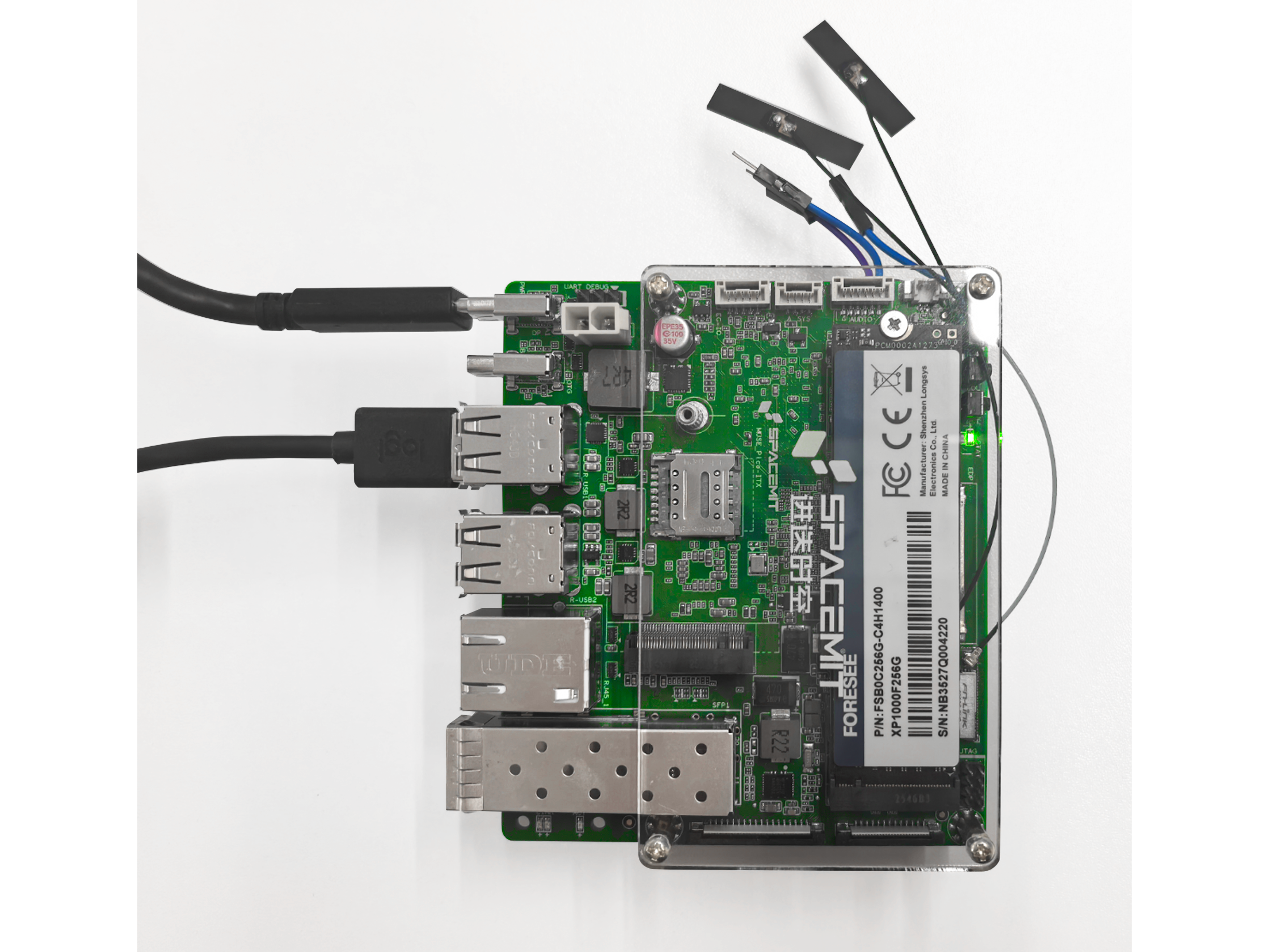
2.1 Board Overview
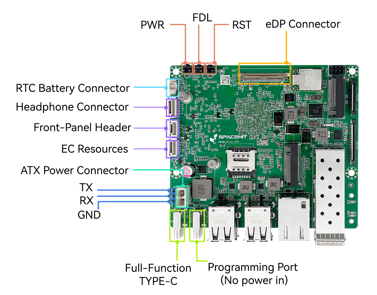
Note: The board appearance may vary slightly depending on hardware revision.
2.2 LEDs and Buttons
| Indicator | Description |
|---|---|
| Status LED STAT | Solid green: system powered on |
Buttons
| Button | Operation Description |
|---|---|
| Power (PWR) | - Press 1s (from shutdown): power on - Press 1s (from standby): wake system - Hold 3s (running): force power off |
| Reset (RST) | - Short press: hardware reset / forced reboot |
| FDL (Firmware Download) | - Hold while applying power or resetting to enter flashing mode |
2.3 Interface Description
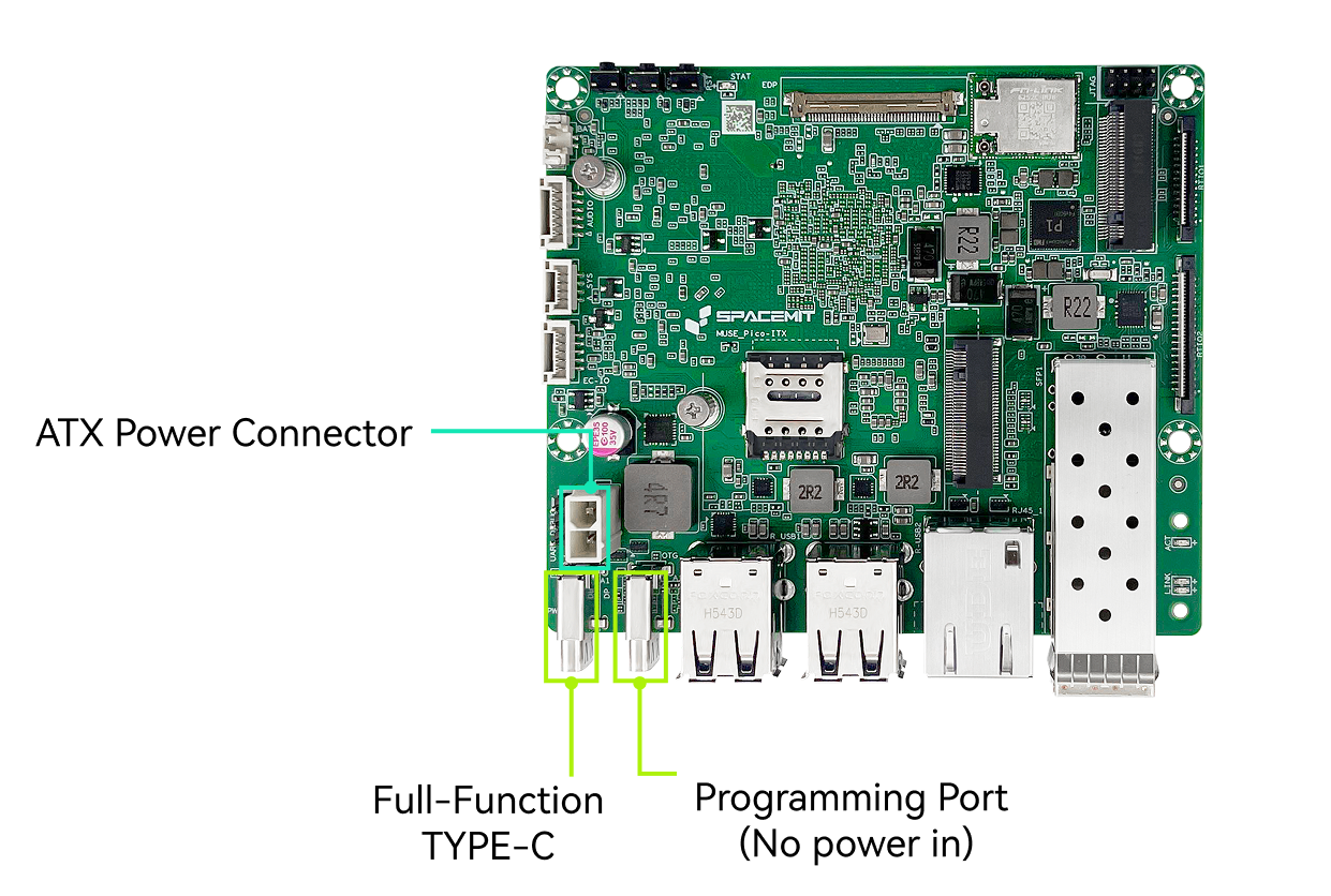
2.3.1 Power Input
- Interfaces: USB Type-C and ATX 2-pin (ATX preferred by default)
- Supports USB-PD 3.0, up to 20 V / 5 A
- Supports direct ATX power input, up to 12 V / 6 A
- In flashing mode, the Type-C port provides both power and USB device connectivity. When connected to a host PC via USB Type-C, the board can be detected and used for firmware flashing and upgrades.s
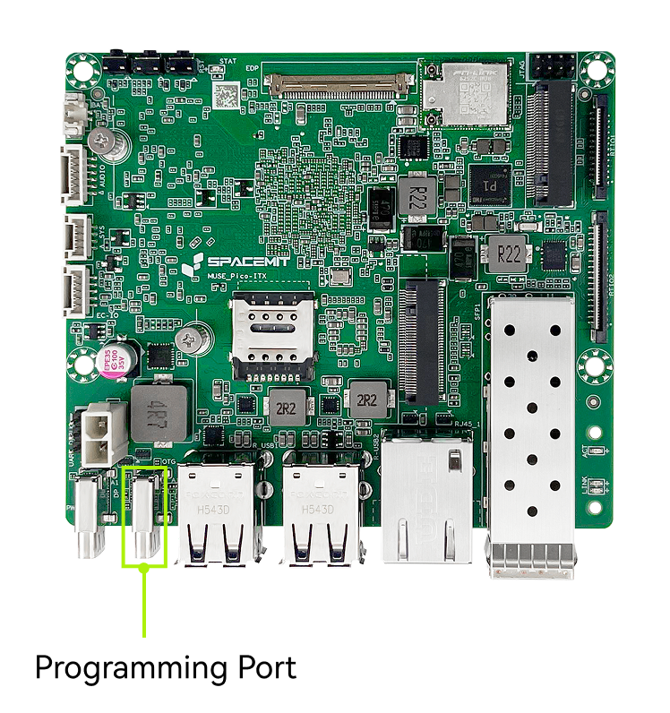
2.3.2 Flashing Interface
When the board enters flashing mode, this port operates as a USB device for data transfer only and cannot supply power to the board. Connect the board to a host computer via USB Type-C to allow the device to be detected and perform firmware flashing or upgrades.
Note:
- The flashing Type-C port cannot power the board. During flashing, the board must be powered through another power input.
- A data-capable USB cable is required. Charge-only cables are not supported for flashing.
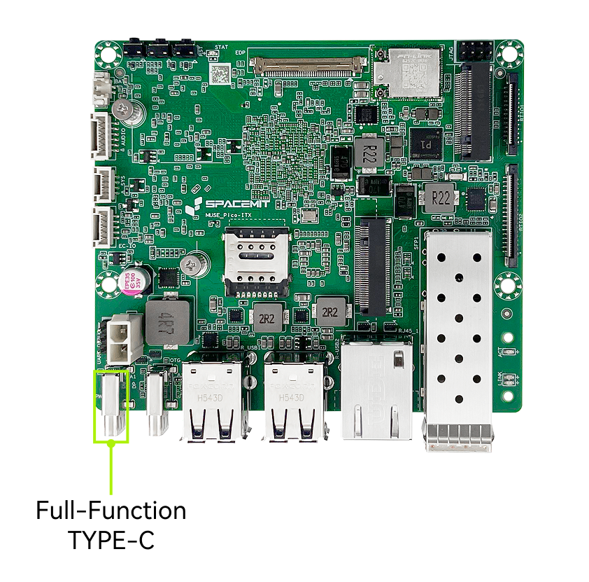
2.3.3 Full-Function Type-C Port
- USB-C connector
- Supports USB-PD 3.0 voltage negotiation
- Supports DisplayPort output
- Supports USB 3.0 peripherals
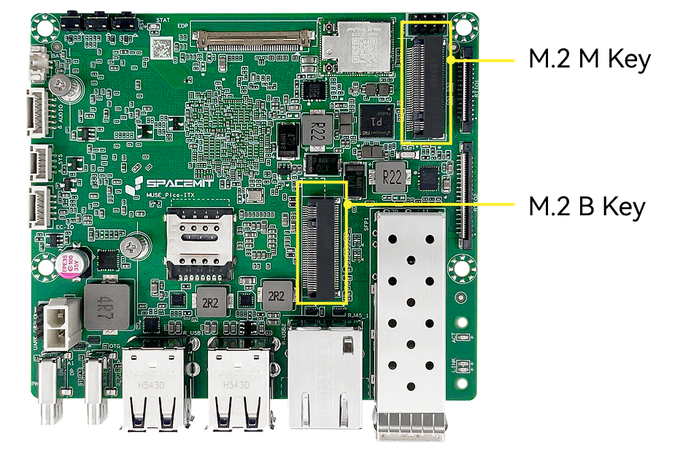
2.3.4 High-Speed Expansion — M.2 M-Key & M.2 B-Key
- Connector type: M.2 connector, 4.2 mm stack height
- M.2 M-Key
- Supports NVMe SSD (2280 form factor)
- PCIe 3.0 ×2 / ×4 bandwidth
- M.2 B-Key
- Supports PCIe SSD (2242 form factor)
- PCIe 3.0 ×2 bandwidth
- Supports USB 2.0 4G modem modules
Notes
- When a PCIe SSD is installed in the M.2 B-Key slot, the M.2 M-Key slot operates at PCIe 3.0 ×2. When the M.2 B-Key slot is unused, the M-Key slot operates at PCIe 3.0 ×4.
- The M.2 B-Key slot supports PCIe SSD only; SATA SSDs are not supported.
- Hot-plugging is not supported. Install or remove devices only when the board is powered off.
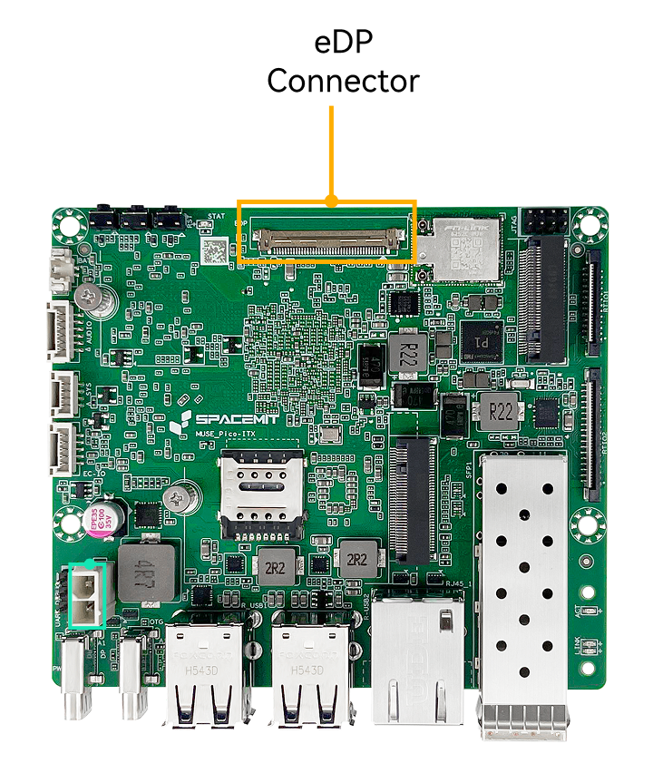
2.3.5 eDP Display Interface
- Connector type: eDP connector
- Supports an external eDP display with a maximum resolution of 2560 × 1600 @ 90 Hz. But hot-plugging is not supported
- When only an eDP display is connected, it is used as the primary display.
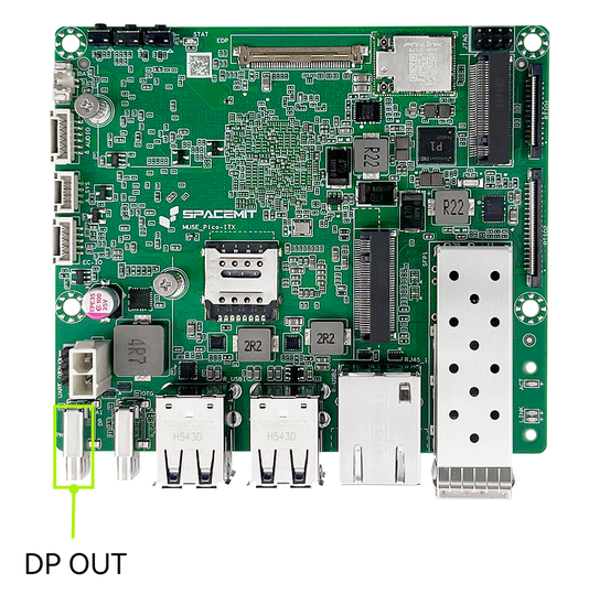
2.3.6 DP Display Interface
- Connector type: USB Type-C (DisplayPort output)
- Supports an external DisplayPort monitor with a maximum resolution of 4K @ 60 Hz. And hot-plugging is supported
- When only a DP display is connected, it is used as the primary display
- When both DP and eDP displays are connected, eDP is the default primary display and DP operates as the extended display. The primary display can be changed to be DP with the operating system settings.
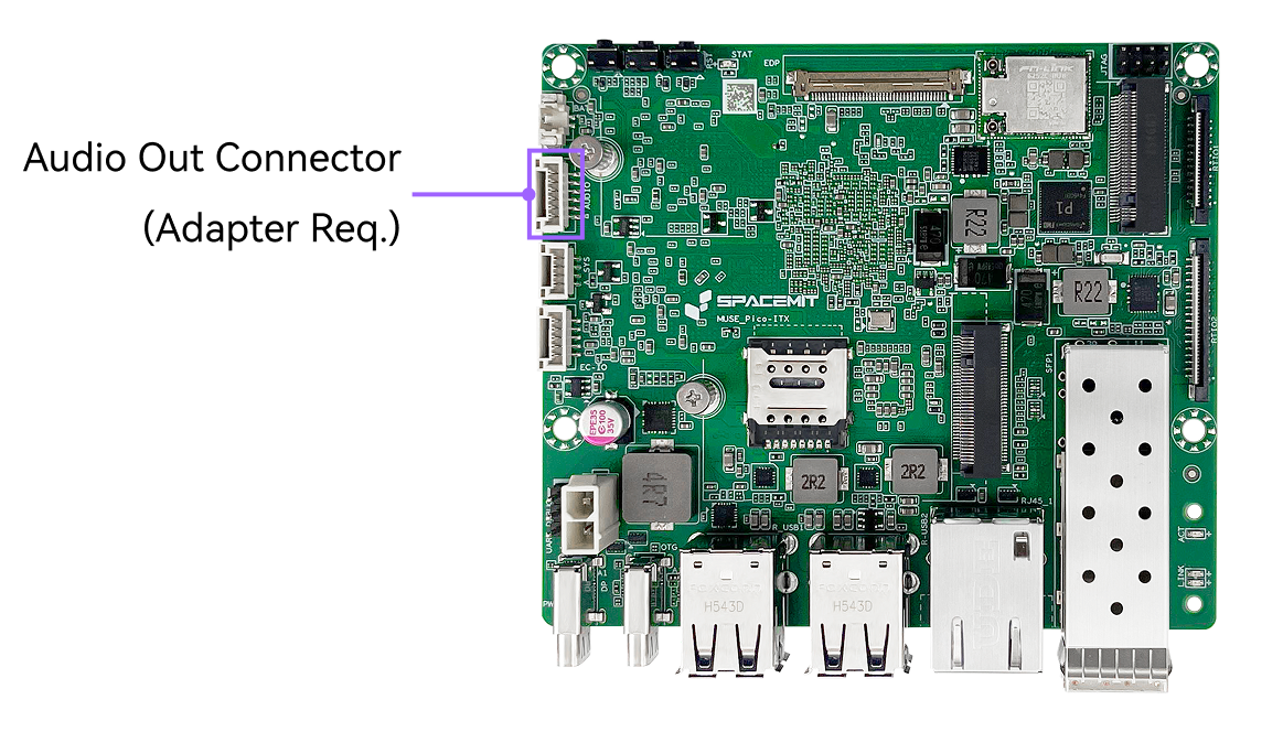
2.3.7 Audio Interface
- Connector type: 1.25 mm latch-type wire-to-board connector
- An onboard audio output header is provided and can be connected to a front-panel 3.5 mm headphone jack using an adapter cable.
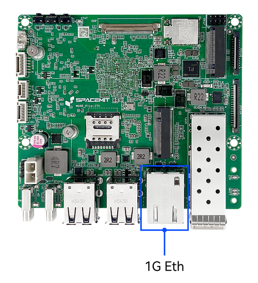
2.3.8 1G Ethernet Interface
- Connector type: RJ45 with integrated green and yellow LEDs
- Supports 100/1000 Mbps auto-negotiation
- Green LED — LINK/SPEED indicator
- Solid green: Link established at the highest supported speed
- Off: Link established but not at the highest speed
- Off: No link established
- Yellow LED — ACTIVITY indicator
- Off: No data transmission
- Blinking yellow: Network activity detected (faster blinking indicates higher activity)
- Off: No link established
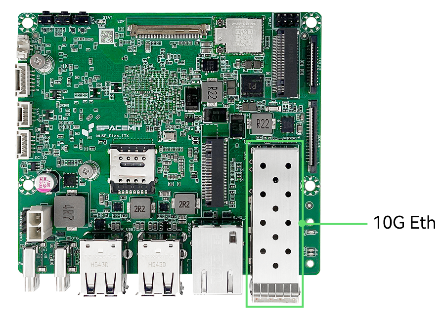
2.3.9 10G Optical Ethernet
- Connector type: Optical (SFP+) port
- Supports 10 Gbps Ethernet
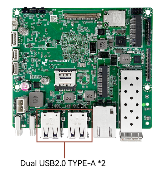
2.3.10 USB 2.0 Interface
- Connector type: USB Type-A
- Plug-and-play, supports USB 2.0 host mode
- Allows connection of multiple USB peripherals such as a keyboard and mouse.
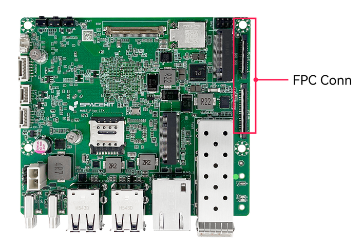
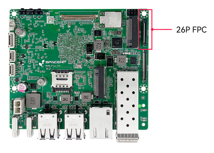
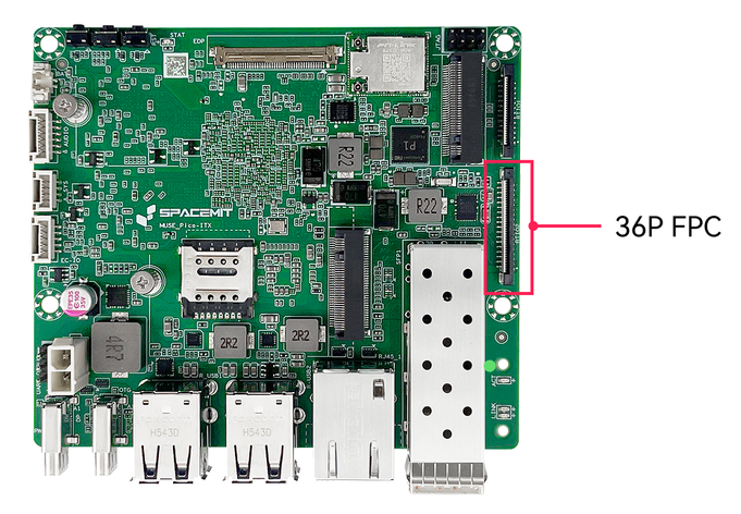
2.3.11 FPC Expansion Connector
- 0Connector type: 0.5 mm pitch, 26-pin + 36-pin FPC wire-to-board connectors
- Provides the following interfaces:
- CAN ×5
- UART ×2
- GMAC ×1
- PWM ×2
- I2C ×1
- SPI ×1
- Supports direct connection to expansion boards
2.4 Specifications
2.4 Product Specifications
| Item | Specification |
|---|---|
| Processor | SpacemiT K3, 8 cores, 2.4 GHz, 60 TOPS general AI performance, compliant with RVA23 standard, supports IME expansion and full virtualization |
| Display | - DP Type-C interface, up to 4K (3840×2160) @ 60 Hz - 40-pin eDP interface, up to 2.5K (2560×1600) @ 90 Hz |
| Memory | Dual-channel 2×32-bit LPDDR5, 6400 MT/s, options: 16 GB / 32 GB |
| Onboard Storage | UFS 2.2, options: 128 GB / 256 GB |
| Storage Expansion | M.2 M-Key connector, supports 2280 NVMe SSD, PCIe Gen3 x4 |
| High-Speed Expansion | M.2 B-Key connector, supports 2242 / 3042 expansion cards, PCIe Gen3 x2 and USB signals |
| Real-Time Expansion | FPC connectors, support EtherCAT, 5× CAN-FD, SPI, I2C, and UART for real-time signal expansion |
| Wireless Communication | Onboard PCIe WiFi6 + BT5.2 module, compliant with 802.11 a/b/g/n/ac/ax, dual-antenna, dual-band |
| Wired Ethernet | 1× RJ45 port, 100/1000 Mbps auto-negotiation |
| Fiber Network | 10G Ethernet, SFP+ port, supports 10G BASE-R / 10G BASE-X, QinQ, MSI-X, WOL, and other network features |
| Audio Interface | Onboard CODEC, supports audio input/output via board headers |
| USB Interfaces | - 2× USB 3.2 Gen1 Type-C (1 full-function, 1 OTG) - 4× USB 2.0 Type-A Host ports |
| Debug Interfaces | Supports UART and JTAG, with 3 side buttons for power, reset, and firmware flashing/upgrades |
| Management System | Onboard EC management system, supports power management, intelligent thermal control, and system status monitoring; provides I2C / UART / GPIO expansion interfaces |
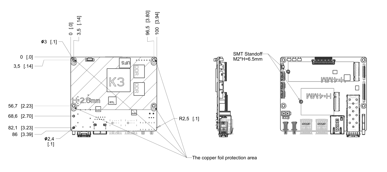
| Form Factor | 100 mm × 86 mm, Pico-ITX Plus form factor, approx. the size of a 2.5" HDD |
| Operating System | Pre-installed Bianbu 3.0; supports Ubuntu 26.04, OpenHarmony 6.0, OpenKylin, Deepin, Fedora, and other OSes |
| Power Input | Dual Type-C USB-PD support, rated 65 W; onboard ATX 2-pin input, 12 V @ 7 A |
| Reliability | - ESD protection (board-level): contact ±4 kV, air ±8 kV - ESD protection (system-level): contact ±6 kV, air ±12 kV - Compliant with CCC, CE, FCC EMC standards - Operating temperature options: Consumer: -20°C ~ 70°C, Industrial: -40°C ~ 85°C |
| Clock | Onboard RTC battery interface, supports battery installation for G3 power-off state |
| Structure | - Optional board-only or with fan-cooled heatsink kit - Optional board-only or custom full-metal industrial chassis - Optional real-time expansion boards, touchscreens, or industrial terminal blocks |
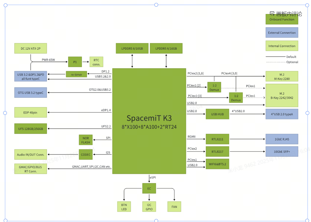
2.5 Block Diagram
3. OS Installation
3.1 Flash via Type-C
Scenario 1: Device Powered Off
- Press and hold the Firmware Flash FDL button.
- Connect a Type-C data cable to the host PC and provide power to the device.
- Release the FDL button.
- Use the official flashing tool Titan or the
fastbootcommand to perform the firmware update.
Scenario 2 — Device Powered On (Type-C Powered)
- Press and hold the Firmware Flash FDL button.
- Short-press the Reset (RST) button.
- Release the FDL button.
- Use the official flashing tool Titan or the
fastbootcommand to perform the firmware update.
Note: For detailed instructions, please refer to the Flashing Tool User Guide .
3.2 Serial Console Debugging
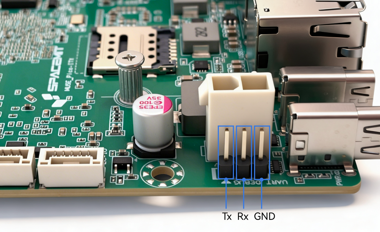
3.2.1 Hardware Connection
Use a USB-to-TTL adapter to connect the host PC to the K3 Pico-ITX UART header using the Tx, Rx, and GND pins as shown below figure. Tx and Rx refer to the transmit and receive signals of the K3 board.
3.2.2 Debugging on Windows (Example: MobaXterm)
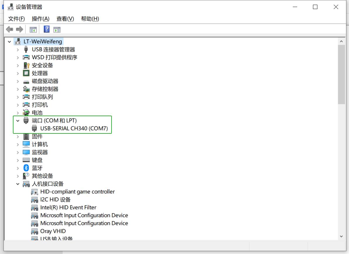
-
Connect the serial hardware correctly and confirm that a COM port appears in Device Manager, as shown below.
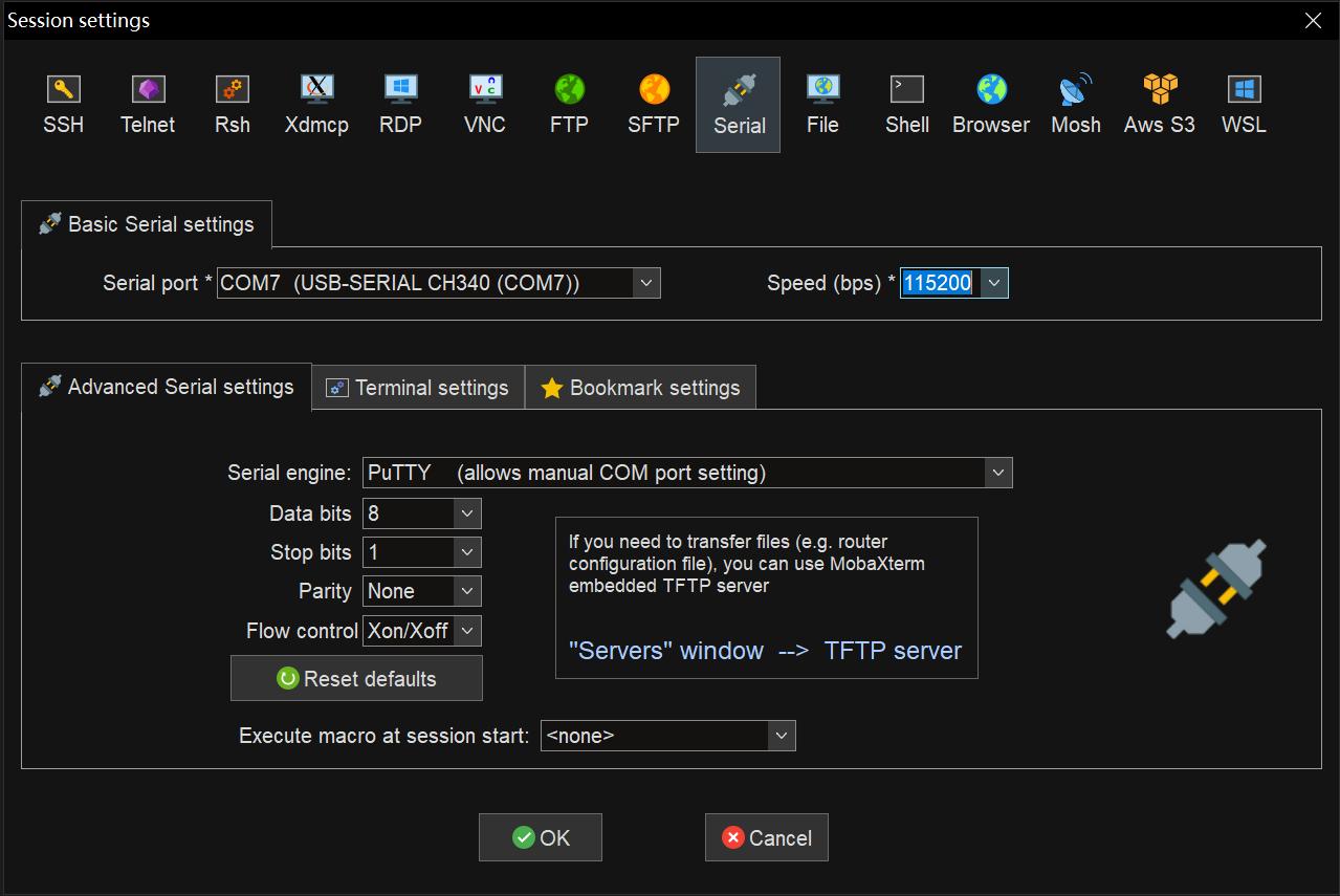
-
Open MobaXterm, then select Sessions → New Session. In the dialog box, choose Serial. Under Basic Serial Settings:
- Set Serial port to the detected COM port
- Set Speed (baud rate) to 115200
-
Click OK to open the serial console and start viewing the log output.
4. Quick Start
K3 Pico-ITX is a single-board computer and requires basic peripherals to get started:
- A power supply
- A monitor
- A keyboard
- A mouse
Connect the required peripherals in advance, then power on the board to start using the system.
Note: A monitor with power delivery capability can also be used to power the board directly via a DP cable.
5. Precautions
The K3 Pico-ITX is suitable for home, office, and industrial environments. Before operating the board, please read the following precautions:
- Do not hot-plug display interfaces, CSI interfaces, or expansion boards under any circumstances.
- Before unpacking or handling the single-board computer, take proper ESD (Electrostatic Discharge) protection measures to prevent damage to the board components.
- When holding the board, handle by the edges and avoid touching exposed metal parts to prevent ESD damage.
- Place the board on a dry, flat surface, away from heat sources, strong electromagnetic fields, radiation sources, or sensitive equipment (e.g., medical devices).
- Ensure the board is in a well-ventilated environment. For continuous full-load operation of 72 hours or more, use the factory-supplied heatsink or implement sufficient cooling measures.
6. Open Resources
Mechanical drawings and dimensions are provided.
7. Appendix — Connector Pinouts
7.1 FPC Expansion Interfaces
The K3 Pico-ITX is equipped with 26-pin and 36-pin FPC expansion connectors.
26-pin Connector Pinout: CAN (from RT24) + I2C (from RT24) + UART + PWM + 3.3V (main power)
| Pin | Signal | Description |
|---|---|---|
| 1 | 3.3V | IO power supply |
| 2 | 3.3V | IO power supply |
| 3 | R_I2C1_SCL | I2C clock |
| 4 | R_I2C1_SDA | I2C data |
| 5 | GND | Ground |
| 6 | R_UART0_TX | UART transmit |
| 7 | R_UART0_RX | UART receive |
| 8 | GND | Ground |
| 9 | UART5_TX | UART transmit |
| 10 | UART5_RX | UART receive |
| 11 | RX_PWM1 | PWM output |
| 12 | RX_PWM2 | PWM output |
| 13 | UART10_TX | UART transmit |
| 14 | UART10_RX | UART receive |
| 15 | UART10_CTS | UART CTS |
| 16 | UART10_RTS | UART RTS |
| 17 | GND | Ground |
| 18 | R_CAN4_TX | CAN transmit |
| 19 | R_CAN4_RX | CAN receive |
| 20 | GND | Ground |
| 21 | R_CAN3_TX | CAN transmit |
| 22 | R_CAN3_RX | CAN receive |
| 23 | GND | Ground |
| 24 | R_CAN2_TX | CAN transmit |
| 25 | R_CAN2_RX | CAN receive |
| 26 | GND | Ground |
36-pin Connector Pinout: GMAC-MII (from RT24) + CAN + SPI + 1.8V (main power)
7.2 UART Debug Interface
- Supports 1×3 single-row pin header for debugging
- Controller side pinout (from bottom to top): GND, Rx, Tx
Note: The board layout may vary slightly depending on the hardware revision.